Session 7.pptx (Lecture Slide)
Microcontrollers and Actuators on Tinkercad
“Microcontrollers think, sensors listen, and actuators do.”
💡 Introduction
Tinkercad by Autodesk is a free, web-based simulation tool that allows students to design circuits, write code, and simulate hardware projects using virtual microcontrollers like Arduino. This session introduces students to the various microcontrollers and actuators available in Tinkercad's Circuits platform, preparing them to build and test electronic and robotics projects without the need for physical components. Tinkercad supports simulation and conceptual learning of various microcontrollers. Each one is suitable for different levels of complexity, and understanding their specifications helps students choose the right controller for their projects.
📘 Pre-requisite Knowledge
- Basic understanding of what a microcontroller is (like Arduino).
- Familiarity with the Tinkercad simulator and its interface.
- Knowledge of electronic components like LED, resistor, motor, etc.
- Simple circuit building skills (connecting components using wires).
- Basic block-based or text-based coding in Tinkercad.
- Understanding of inputs (sensors) and outputs (actuators).
🎯 Learning Objectives
- Understand the Tinkercad Circuits environment.
- Identify various microcontrollers available in Tinkercad.
- Learn about common actuators and their uses.
- Perform simple simulations using microcontrollers and actuators.
🛠 Tools & Materials Required
- Hardware: Laptop / Desktop.
- Software: Tinkercad.
- Others: Internet connection.
Microcontrollers in Tinkercad
1. Arduino Uno R3
Arduino Uno R3 is one of the most popular open-source microcontroller boards, based on the ATmega328P microchip. It is fully supported by Tinkercad and is ideal for beginners and advanced learners alike.

Specifications:
- Microcontroller: ATmega328P.
- Operating Voltage: 5V.
- Digital I/O Pins: 14 (6 can be used as PWM outputs).
- Analog Input Pins: 6.
2. BBC Microbit
The BBC Microbit is a pocket-sized computer designed specifically for education. While not natively supported in the Tinkercad Circuits editor, students are often introduced to its features as part of cross-platform knowledge.

Specifications:
- Microcontroller: Nordic nRF51822.
- Operating Voltage: 3V (via battery or USB).
- Digital I/O Pins: 19 GPIO.
- Analog Inputs: 3.
Built-in Features:
- 5x5 LED matrix display.
- 2 programmable button.
- Accelerometer.
- Magnetometer (Compass).
- Bluetooth Low Energy (BLE).
- Temperature Sensor.
3. BBC Microbit with Breakout Board
A Microbit with Breakout Board offers easier access to the microbit’s I/O pins, allowing it to be connected to more external components, such as motors, sensors, and displays.

Specifications:
- Access to all 20 GPIO pins through labelled headers.
- Power Supply Pins: 3.3V, GND.
- Improved circuit-building capability for classroom or prototyping projects.
4. ATtiny85
The ATtiny85 is a compact and low-power microcontroller from Atmel, part of the AVR family. It’s commonly used in small-scale embedded applications however, it's essential for students to learn its capabilities and how it fits in the microcontroller ecosystem.

Specifications:
- Microcontroller: ATtiny85.
- Operating Voltage: 2.7V to 5.5V.
- Digital I/O Pins: 6 (including 3 PWM outputs).
- Analog Inputs: 4.
Actuators in Tinkercad
An actuator is a device that converts electrical signals into physical action or movement. In electronics and robotics, actuators are used to control motion, sound, light, or mechanical responses based on signals from sensors or microcontrollers. Actuators are an essential part of embedded systems and automation projects because they allow systems to interact physically with the environment. In Tinkercad, actuators are used to demonstrate how virtual microcontrollers can control outputs like motors, lights, and sounds in a simulated circuit.
Below is a list of the most used actuators in Tinkercad Circuits, with full descriptions:
1. Piezo Buzzer
A piezo buzzer produces sound based on the vibration of a piezoelectric material. It emits a tone when a voltage is applied across it.


Specifications:
- Operates on 3V–5V.
- Has two pins: positive (+) and negative (–).
- Can generate sound signals via PWM or tone() function in Arduino
2. LED (Light Emitting Diode)
An LED is a basic light-emitting device that turns on when current flows through it in the correct direction.

Specifications:
- Comes in multiple colours (Red, Green, Blue, etc.).
- Requires a current-limiting resistor to avoid damage.
- Turns ON/OFF using digital pins, and brightness can be adjusted using PWM.
3. RGB LED
An RGB LED combines three LEDs (Red, Green, and Blue) in a single package to produce a wide range of colours.

Key Features:
- 4 pins: Common Cathode/Anode + R, G, B.
- Controlled using PWM on three pins.
- Can create different colours by mixing intensities of RGB.
4. Servo Motor (SG90)
A servo motor is a rotary actuator used for precise control of angular position. It rotates between 0° and 180°.


Specifications:
- Operates on 5V.
- Three wires: Signal (Orange/Yellow), VCC (Red), GND (Brown/Black).
- Controlled using PWM signals to set angle.
5. DC Motor
A DC Motor converts electrical energy into continuous rotation.


Specifications:
- Two terminals for power input.
- Direction of rotation depends on polarity.
- Speed controlled via PWM, direction via H-Bridge motor driver.
6. Hobby Gearmotor
A Hobby Gearmotor is a type of DC motor with an integrated gearbox that reduces the motor’s speed and increases its torque (rotational force). This allows the motor to drive heavier loads or move with more precision at slower speeds.


Specifications:
- Voltage Rating: Typically, 3V to 6V (depends on model).
- Pins/Terminals: Two (Polarity-sensitive for direction).
- Speed: Reduced RPM due to gear ratio.
- Torque: Higher torque due to gear reduction.
- Control: Requires an H-Bridge motor driver or transistor with PWM signal.
- Mounting: Usually includes screw holes for easy attachment to chassis.
7. Vibration Motor
A Vibration Motor is a compact actuator that vibrates when powered. It contains a small, unbalanced mass on its shaft which causes it to vibrate when the motor spins.


Specifications:
- Voltage Rating: 3V to 5V.
- Pins: Two (Power + Ground).
- Control: Simple ON/OFF using digital output pin or transistor.
- Current Draw: Typically, low (~60-100 mA).
- Form Factor: Cylindrical or pancake-style with mounting tape.
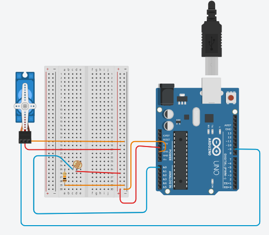
Activity- Light-Controlled Servo Gate
Simulate a gate system that opens when light level increases, using LDR (Light Sensor) and Servo Motor with Arduino in Tinkercad.
Components Used:
- Arduino UNO.
- Servo Motor.
- LDR Sensor.
- Resistor (10KΩ).
- Breadboard.
Code:

Circuit Diagram:
Servo Motor Pin |
Connect To |
|
VCC |
5V on Arduino |
|
GND |
GND on Arduino |
|
OUT |
D9 on Arduino |
LDR Pin |
Connect To |
|
Terminal 1 |
A0 on Arduino |
|
Terminal 2 |
5V on Arduino |
10 KΩ Resistor Pin |
Connect To |
|
Terminal 1 |
GND on Arduino |
|
Terminal 2 |
Terminal 1 of LDR |
🧩 Expected Outcome
Activity: https://www.tinkercad.com/things/1d6ayXBXSXp-ldr-controlled-servo-gate
🔍 Observation
- Use the Tinkercad platform to simulate and experiment with microcontrollers and actuators.
- Learn how to connect actuators to microcontrollers in a circuit diagram.
- Understand how digital and analogue pins are used to send control signals to actuators.
- Design circuit-based solutions for real-life challenges using actuators.
- Understand the interaction between sensors, microcontrollers, and actuators in a smart system.
There are no comments for now.